A friend recently commented that model railroading is the predecessor to modern online "Role Playing Games". So be it. But, if you have a model railroad and you want to operate it "realistically," what is the "best" approach? Are we all searching to answer this question?
I have a large HO layout in the basement that takes 15 operators over about 15-20 hours of playing time to operate a prototype day of trains "realistically". I started out using hand written car cards and waybills, and graduated to computer-generated waybills, using a program called "Waybills" by Shenware Software. (about $50). I like the computer generated waybills because they're easier to read, I can put my SPINS numbers on each destination easily, they can have color codes for destination and railroad, and most people know how to use them. Our longest trains are in the range of 25-30 cars, which is a large handful of car cards to keep track of, but they all fit in a single car card box when needed (if you insert them upside down). Also, the program gives you access to all the locations on the OPSIG's industries database, and allows you to analyze the number of waybills you have set up for each shipper on the railroad, for balancing traffic. So far so good.
Joe Green has an approach where he has either himself or the train conductor sit down with the car cards and waybills and manually prepare a switchlist for the train crews. There is some additional realism to this, although it also creates extra paperwork (albeit "realistic").
As an experiment, I've recently set up JMRI ops for my N scale (4'x8') railroad and tried "building" train switchlists. There are a lot of features to this open-source program, so I'm still on the very steep part of the learning curve, but I will say it's fun.
It seems to me that the key to understand car routing is that there are two distinctly different types of cars - "captive" and "free". A captive car runs between, say, a mine and a mill, and doesn't get diverted someplace else - it just runs back and forth. A free car can be "confiscated" any time it is empty, and sent someplace to be loaded so that it can progress in the general direction of its "home" road. For captive cars, depending on the complexity of the layout, you don't need any paperwork at all, because it's obvious that the empty log cars go back to the log camps. For captive cars without open loads, you need a waybill or switchlist to know if the car is empty or loaded, but after that, again, the move is relatively obvious. But are you just running them back and forth, or do the cars need to be cleaned, and/or stored in a yard, between moves? I have a bunch of (captive) cement cars that move between Lonestar Cement in South Seattle and a dam site in Concrete, and their waybills only have two cycles. But should I add two more intermediate destinations, to a clean-out track and a holding yard? What about weighing the loaded car? That would make 5 cycles, which is hard to do with a 4 cycle waybill. What I do presently is to add a note "weigh at scale" to the loaded move, so the operators know to run it through the scale track before forwarding it on to Concrete. Another option would be to remove the waybill at Concrete and have the cars return back to Lonestar per an instruction written on the car card itself.
For free cars, in general, they arrive inbound with some kind of load, get emptied, and then either sent back empty to where they came from (staging), or confiscated to a local industry to be sent back loaded (to staging). This could be two moves, or three, or four, or more, depending on if they get stored at an empty car track in a yard, cleaned, or weighed after the second loading. I imagine that JMRI ops can take care of all of that, but I'm not far enough up the learning curve to discuss how. My car cards and waybills generally can handle these variations ok.
But not really, because the process of confiscating cars is done on the fly by railroad agents and clerks, and not prescribed on a waybill. It seems to me a better approach would be to remove the waybills after the car is unloaded, and give the yardmasters a stack of new waybills to insert in empty cars as they see fit, while they are switching the yard. But, would they do it? My experience as a model railroad yardmaster is that it's all you can do to keep up with the incoming and outgoing trains, without also making decisions about what to do with empties. Not to mention where to store them, since there are never enough yard tracks. I don't know. Maybe we'll try this and see what happens.
But to do this with JMRI on the fly would really be challenging. You could do it, though, because JMRI's "move" option allows the program to continuously update the status of the cars on your train as you move along your train's route. It would involve only building trains and switch moves "just in time", rather than printing them out before the session started. But someone would be tied to the computer during the op session, for sure. How many model railroaders come to op sessions wanting to be clerks?
Friday, January 31, 2020
Thursday, January 16, 2020
improving electrical reliability of Shinohara turnouts
Electrical reliability is a key to enjoyable model railroad operations. If you have a lot of older Shinohara (later bought by Walthers) brand turnouts, which are "point-activated, power-routing" turnouts, you can have issues with electricity not reliably passing between the stock rails and the points, or with the electricity not making it from the points to the frog area. You can see one of these older turnouts in the lower foreground of the photo below of some operating action at Everett's Bayside yard:


I'm not likely to replace this turnout soon, since it's in the middle of a road crossing and is already ballasted. The best solution, in most situations, is installing a "Frog Juicer" (trademark of Tam Valley) - a circuit which monitors the center portion of the turnout and flips its polarity whenever it detects a short. I've installed a lot of these, and they work great. The juicer is hooked up to the center rails near the frog, so it doesn't care if there is contact between the points and the rest of the turnout.
However, to save time and money, I sometimes resort to simply soldering a small feeder wire between the switchpoints assembly and the inner fixed part of the turnout. It's not as elegant or foolproof as the frog juicers, but it significantly improves electrical reliability, as long as I keep the switchpoints clean so they will conduct electricity from the stock rails. Here are photos of several variations:


The idea above is to take the wire away from the turnout so that it can be covered up by ballast later on, and won't show. This only works if you haven't ballasted the turnout yet, though.

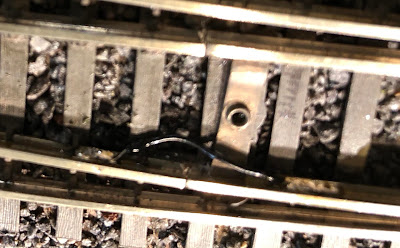
Here, slightly out of focus, on a turnout already ballasted, I just soldered a small wire directly on the inside web of the rail. You have to be careful to keep the solder and wire below the level of the wheel flanges, though. I could have kept the wire straight to make it less visible, but I like the idea of giving it more room to flex (probably unnecessary).

On this one I wrapped the (bare) wire in a faux-spring loop, to give it more flex. But I realized later that it would have been better just to use a much thinner wire. (note to self - paint this wire darker sometime!)
Incidentally, the photo above also shows what we do here to make turnouts easy to understand. I got the idea from Al Frasch - when the turnout is selected for the "through route" (which in this case happens to be the curved one), the switch machine handle shows yellow and exposes the yellow pin. The red pin is (somewhat) covered up by the handle, so you can see at a glance that this switch is set to "yellow". If the ground throw was thrown to the other side, the handle would cover up the yellow pin and would show its red side, in addition to exposing the red pin. I've heard that some layout owners arrange it the opposite way. I got used to this convention at Al's layout, so I stuck with it. Also, the yellow color of the through route indicates that the turnout is not on the mainline. All turnouts on the main have green pins for the through route, instead of yellow. This also helps people in keeping track of which track (s) is(are) the main track(s).
The final step is always testing, so here's an innocent FM switcher trying out an old (early Walthers, in this case) power-routing turnout after installation of the black wire in the out-of-focus photo above. The headlight is lit - so far, so good!

Tuesday, January 14, 2020
creating dispatcher panels using JMRI
"Nothing worthwhile is easy" may or may not be true, but it is true that (a) dispatchers on the Burrlington Northern have repeatedly asked to be able to control the turnouts at the Delta Wye and along the double track main, (b) those turnouts were already controlled by "accessory decoders" reachable on the NCE DCC system, (c) I already had set up a USB connection between my laptop and the NCE DCC system, and (d) it was easy to procrastinate diving into the steep learning curve of building such panels using the JMRI DecoderPro and PanelPro open-source software.
In the end, though, it only took about 6 hours of focused concentration and youTube video watching to get the job done. I'm not saying it was fun or easy, I'm just saying that it is doable, and even rewarding. The JMRI software is an extremely complex set of tools, with many features, but to get this job done I had to just focus on three things: (1) how to create software labels for each turnout (and make sure it is stored in memory forever), (2) how to lay out the track on the panel, and (3) how to connect the panel switches to the correct turnout labels. Not to mention step (0), which is figuring out how to download the software and open up the needed tools - also a complex undertaking in itself.
So, here's a screenshot of the "turnout table" that I ended up with, showing each controlled turnout. This had to be created before connecting panels to them.

The system name for each turnout "NTxx" is simply the two (or more, if needed) digit address of the "stationary decoder" on the layout that drives that turnout. The user name is whatever I call that turnout verbally.
The next steps are to lay out the track diagrams, using their faux-CAD tools, and then to link each turnout on the diagram to its corresponding NTxx address. It took longer to figure out how to do it, than to do it. Here is the final result: a set of track diagrams on the laptop allowing the dispatcher to control the key turnouts. By clicking the mouse over each controlled turnout, the software sends a message to the NCE system to set the turnout to the desired position.

Now that this is done, I feel sheepish that it took so long to "get around to it", considering how useful this will be to dispatchers for all future op sessions.
But in case you think I'm declaring victory, consider this: How will the dispatcher know which way the turnout is thrown, if an operator out in the field has thrown the switch using the toggle switch or push buttons on the front of the benchwork next to the turnout? The only way would be to cycle the turnout on the laptop control panel, which would derail any train that might be on that track being used locally. Now I need to install toggle switches at each turnout to clarify if the turnout is under dispatcher control or local control. And this would be only the crudest way to do it. A better way would be with sensors and position lights, so the dispatcher could see which way the toggle switch was thrown, etc. Not to mention trackside signals. As usual, one thing leads to another! Argh!
Monday, January 6, 2020
adding a run-around to the Woodinville branch
The Burrlington Northern seems like a continuous exercise in taking short cuts first, and coming back later and spending a bunch of time to get it right. As they say, "there's never enough time to do it right, but there's always time to do it over," or something like that. Also, as much as I might plan ahead, later on I find out new things I didn't know before, and go back and modify the layout afterwards. Such is the case with the Woodinville Branch.
The Woodinville Branch wasn't on my radar when I planned the layout, since I was busy enough with building both Everett yards (Delta and Bayside) and the Burlington yard further north. But one day Bill Sornsin was over here, generally approving of how things were going, and, while looking at Delta yard, he enthusiastically said "Hey, you could run the Woodinville local out of here!" With a heavy heart, I immediately knew that he was right, and I would make a new project out of creating an intermediate level deck somewhere that could be operated as the Woodinville branch.
There's a lot to be said for it. For starters, it served a number of towns where people who run trains on the layout actually live in real life today, such as Issaquah, Redmond and, of course, Woodinville. This would help make the layout familiar to operators who don't get up to Everett and Burlington that often. Plus, at the beginning of the branch, it climbs a steep grade from Snohomish to Maltby, which could justify taking a steep climb up to an intermediate-level deck on the wall of the layout room, and limiting train length to something manageable, like, say, 5 cars.
So, surveys were conducted, plywood was cut and painted, track laid and wired up, and the Woodinville Local took its rightful place in the lineup of trains operating on the Burrlington Northern each operating session. I did the project in a big hurry, was very limited in the width of the space available, and decided to limit it to a single trailing point, and two facing point, spurs. I called them Woodinville, Redmond and Issaquah, respectively, parked a few cars on them, made up some waybills, and called it good. But there was no run-around, no siding, just three spurs. What the heck, I figured, we'll stage the SD9 (needed for tractive effort on the 5% grade getting up there) on the trailing point spur (track #2620 in the diagram below) , and then the local can assemble whatever cars are there, haul them down to Everett, bring some new cars up (loco pushing uphill at the back) and shove them into their respective spurs.

It has been operating like this for a couple of years now. Mission accomplished:

But not really. First of all, the Woody Local (as it was called) started its run in Delta yard, not in Woodinville. And second, without a runaround track on the shelf, how much of a switching puzzle can it really be? It's just two staging tracks with an engine pocket.
So, the survey crew got to work and figured out a way to add a switch with a tail track about 4 car lengths long to provide a run-around option for crews in Woodinville:

Then, the construction crew got to work on adding a piece of plywood and modifying the underlying scenery:

And the tracklaying crew followed:

And now the runaround track and tail track are operational on the Woodinville branch:

It's not pretty yet, but it'll get there. Now the operator(s) will have all the extra fun of getting the loco and caboose out of the Everett engine terminal and calling a crew for the run up the hill, with a more complex switching puzzle to work on when they get there. Much more like the real thing.
On the other hand, this assumes that you enjoy switching against the wall with only about 6" of clearance between the track and the deck above. Adding a runaround track to any two-track "staging shelf" could actually take away its staging capacity, depending on how much capacity is available outside of the runaround tracks themselves. So, we will try operating the "new" Woodinville branch, and see how we like it. Stay tuned!
The Woodinville Branch wasn't on my radar when I planned the layout, since I was busy enough with building both Everett yards (Delta and Bayside) and the Burlington yard further north. But one day Bill Sornsin was over here, generally approving of how things were going, and, while looking at Delta yard, he enthusiastically said "Hey, you could run the Woodinville local out of here!" With a heavy heart, I immediately knew that he was right, and I would make a new project out of creating an intermediate level deck somewhere that could be operated as the Woodinville branch.
There's a lot to be said for it. For starters, it served a number of towns where people who run trains on the layout actually live in real life today, such as Issaquah, Redmond and, of course, Woodinville. This would help make the layout familiar to operators who don't get up to Everett and Burlington that often. Plus, at the beginning of the branch, it climbs a steep grade from Snohomish to Maltby, which could justify taking a steep climb up to an intermediate-level deck on the wall of the layout room, and limiting train length to something manageable, like, say, 5 cars.
So, surveys were conducted, plywood was cut and painted, track laid and wired up, and the Woodinville Local took its rightful place in the lineup of trains operating on the Burrlington Northern each operating session. I did the project in a big hurry, was very limited in the width of the space available, and decided to limit it to a single trailing point, and two facing point, spurs. I called them Woodinville, Redmond and Issaquah, respectively, parked a few cars on them, made up some waybills, and called it good. But there was no run-around, no siding, just three spurs. What the heck, I figured, we'll stage the SD9 (needed for tractive effort on the 5% grade getting up there) on the trailing point spur (track #2620 in the diagram below) , and then the local can assemble whatever cars are there, haul them down to Everett, bring some new cars up (loco pushing uphill at the back) and shove them into their respective spurs.

It has been operating like this for a couple of years now. Mission accomplished:

But not really. First of all, the Woody Local (as it was called) started its run in Delta yard, not in Woodinville. And second, without a runaround track on the shelf, how much of a switching puzzle can it really be? It's just two staging tracks with an engine pocket.

Then, the construction crew got to work on adding a piece of plywood and modifying the underlying scenery:

And the tracklaying crew followed:

And now the runaround track and tail track are operational on the Woodinville branch:

It's not pretty yet, but it'll get there. Now the operator(s) will have all the extra fun of getting the loco and caboose out of the Everett engine terminal and calling a crew for the run up the hill, with a more complex switching puzzle to work on when they get there. Much more like the real thing.
On the other hand, this assumes that you enjoy switching against the wall with only about 6" of clearance between the track and the deck above. Adding a runaround track to any two-track "staging shelf" could actually take away its staging capacity, depending on how much capacity is available outside of the runaround tracks themselves. So, we will try operating the "new" Woodinville branch, and see how we like it. Stay tuned!
Thursday, January 2, 2020
the train-mounted camera
When people visit the layout in between op sessions, they always enjoy seeing the live view from the locomotive cab window. In the picture below, you can see the TV monitor to the right of the dispatcher's panel, displaying the view as the camera train makes its way through the Stacy St. yard in Seattle (directly in front of me as I reach over to fix something in the Burlington yard on the upper deck). You can also see the stairs and household plumbing along the wall, and the overhead fluorescent and track lighting. The grey industrial complex in the upper left is NW Olivine, a company on the Concrete Branch that supplies fine sand to locomotive facilities, among other customers. This makes for an unusual, although prototypical in this case, on-layout to on-layout shipper/receiver pair.

Back to the camera train - it is installed in an old Athearn F-unit (shown in the photo below) with power coming from the DCC voltage on the track. Look carefully and you can see the 4" flexible antenna sticking out from the cab. It transmits the video stream to a receiver in the center of the room, which then sends an old fashioned video signal across VCR type wires along the ceiling and down the side of the stairway to the TV monitor. To make room for the camera and power supply, I took the motor and drive gears out of the F-unit, so it has to be pushed by something else. Ideally we could have a sound decoder and speaker in it as well, hooked up to a headlight and consisted with the trailing units. Some day...

In theory, one could operate a train while sitting next to the dispatcher and reading hand signals from a brakeman walking next to the train as it moves around the layout (and using a ProtoThrottle for realistic locomotive control, of course). I think many people would find this fun. So far, the operating sessions have been so chaotic that nobody felt relaxed enough to try this, (or even the ProtoThrottle, for that matter) but the tools are in place, so someday it may happen.
Subscribe to:
Posts (Atom)