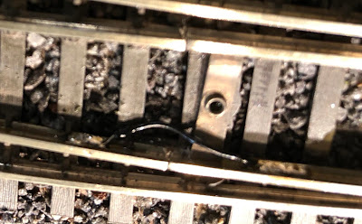
I'm not likely to replace this turnout soon, since it's in the middle of a road crossing and is already ballasted. The best solution, in most situations, is installing a "Frog Juicer" (trademark of Tam Valley) - a circuit which monitors the center portion of the turnout and flips its polarity whenever it detects a short. I've installed a lot of these, and they work great. The juicer is hooked up to the center rails near the frog, so it doesn't care if there is contact between the points and the rest of the turnout.
However, to save time and money, I sometimes resort to simply soldering a small feeder wire between the switchpoints assembly and the inner fixed part of the turnout. It's not as elegant or foolproof as the frog juicers, but it significantly improves electrical reliability, as long as I keep the switchpoints clean so they will conduct electricity from the stock rails. Here are photos of several variations:
The idea above is to take the wire away from the turnout so that it can be covered up by ballast later on, and won't show. This only works if you haven't ballasted the turnout yet, though.
Here, slightly out of focus, on a turnout already ballasted, I just soldered a small wire directly on the inside web of the rail. You have to be careful to keep the solder and wire below the level of the wheel flanges, though. I could have kept the wire straight to make it less visible, but I like the idea of giving it more room to flex (probably unnecessary).
On this one I wrapped the (bare) wire in a faux-spring loop, to give it more flex. But I realized later that it would have been better just to use a much thinner wire. (note to self - paint this wire darker sometime!)
Incidentally, the photo above also shows what we do here to make turnouts easy to understand. I got the idea from Al Frasch - when the turnout is selected for the "through route" (which in this case happens to be the curved one), the switch machine handle shows yellow and exposes the yellow pin. The red pin is (somewhat) covered up by the handle, so you can see at a glance that this switch is set to "yellow". If the ground throw was thrown to the other side, the handle would cover up the yellow pin and would show its red side, in addition to exposing the red pin. I've heard that some layout owners arrange it the opposite way. I got used to this convention at Al's layout, so I stuck with it. Also, the yellow color of the through route indicates that the turnout is not on the mainline. All turnouts on the main have green pins for the through route, instead of yellow. This also helps people in keeping track of which track (s) is(are) the main track(s).
The final step is always testing, so here's an innocent FM switcher trying out an old (early Walthers, in this case) power-routing turnout after installation of the black wire in the out-of-focus photo above. The headlight is lit - so far, so good!


No comments:
Post a Comment