Thursday, December 16, 2021

Adding a second deck for the narrow gage - Part 1


There's going to be a new narrow gage town on the Burrlington Northern soon! This just shows a mock-up, but there is more to come. The square hole in the backdrop, in the upper right hand corner of the photo, shows the current "end of track" where the narrow gage winds up a helix between some heading ducts. A short stretch of trestles and bridges will get it over to this proposed shelf, made of 1" Gatorboard. At the moment I am mocking up the proposed new upper deck, to see how it will affect lighting on the deck below and other considerations of feasibility and desireability. Here's a photo of it from below:


Of course we will paint the bottom sky blue to increase reflected light on the lower deck, and give it a backdrop, but as you will see in the photos below, thanks to the low angle of the already existing track lights, the effect of this massive shelf on the lower deck is surprisingly minimal. Here's another shot, taken from even higher than my 70" eye level:


This deck, at about 68" above the (slightly sloping) floor, will be visible at eye level to tall people like me, and operable by anyone with a suitable stool. It's an important strategic addition because it gives the narrow gage line "someplace to go" beyond the already exising intermediate towns of Paradise and Hope. In addition to this new town, I also plan to wrap the line around the corner to the left and build a combination staging yard and stock pen(s). There couldn't be a better time to work on this, because in Sept 2022 the National Narrow Gauge Convention will be held in nearby Tacoma and people from around the world might want to come egg me on. Or, maybe I could take one of the removable modules down to the convention for viewing. But, I'm getting ahead of myself...

Here's a final shot (for today) of that further addition mocked up - note how little it interferes with the lower deck lighting. The next step is to finalize the supporting brackets. One of my goals for the project is to have each of these shelves easily removable so we can do most of the modeling at the workbench rather than up that close to the ceiling. Any comments or suggestions are appreciated! I am really liking the dimensional stability of these 1" Gatorboard panels, but this is the first time I've tried using them for a layout base. Will keep you posted...










Thursday, November 4, 2021

Sand Towers at Interbay, Part 3

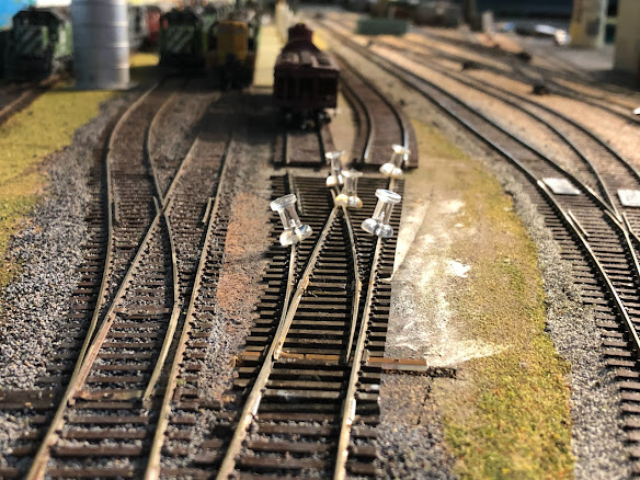
 Work continues on the Interbay Engine Terminal's sand tower project. Here is an overview from the south looking north, showing that I removed one of the existing tracks and replaced a number 6 switch with a wye switch, in order to make room for a concrete pad to support the sand towers. Dave Enger built the pads out of sheet styrene, which you can see are temporarily in position. The BN mainline is the track to the left of the construction site, with grey ballast and raised above the rest of the yard.


Here is a detail view of the approximate track alignment, showing that we'll have to cut part of the concrete pad to accommodate the curving track


And finally, here is a view from the north looking south, showing that we've added a new turnout to provide a short track for loading sand, oil and water to the various dispensers that will be on the locomotive service pad. I doubt this track was there on the prototype in this exact location, but it's where we have room for it, so there it is. It will be fun to spot cars there during op sessions. Especially since we have a model of Northwest Olivine on the Concrete Branch, which was the source for this high quality locomotive sand, making it one of those rare prototypical on-layout origin/destination pairs.


Monday, November 1, 2021

Sand Towers at Interbay, Part 2


Here's a better close-up of the Interbay sand towers that we're trying to model. One early design decision we had to make was how far north or south to located them in my condensed HO scale version of the Interbay Engine Terminal. Below are two photos, with the mocked up towers positioned to the right (south) and left (north). We didn't consider going all way to the north, because I wanted to allow room for a short spur for unloading sand cars. More on that in a later post.


Based on these mock-ups, we've decided to locate it to the right, as shown in the upper photo here. Next up will be to install the concrete pavement between the tracks and re-install the track.


Friday, October 22, 2021

The Sanding Towers at Interbay Engine Terminal


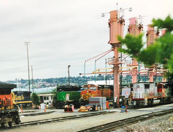
Here's a view of the (prototype) Interbay Engine Terminal, looking north, about 1995. I don't know when these towers were installed, but let's just assume that we "need" these on my model of the Interbay Engine Terminal. The only thing is, just a few weeks ago we "finally" got around to ballasting the tracks there, and there isn't a space between any of the tracks. You know what this means. Rip up something we just did a month earlier. Love it.

So, we decided there was room to move one track over and create the space for a model of this. Despite the obvious stupidity of this, I'm pretty excited about it. These sand towers are really going to add some excitement to the engine hostler job at Interbay! All I can report today is that Dave Enger is mocking up a scratch-built version of the towers, and I've removed the offending track. See photo below. Stay tuned...


Sunday, September 26, 2021

Should we lengthen the siding at Everett's Bayside Yard?


The short answer is "no". Here you see the very skeptical Bill Messecar and Dave Enger having a discussion with me about moving the south turnout of Bayside yard from behind Bill's shoulder on the left to underneath Dave's hand on the right. While installing a turnout on the "squid bridge" is not "impossible", the larger question is whether it is "worth it". Fortunately, I build the main curve far enough away from the 6x6 column (which supports two stories of house above it!) to make such an extension possible. But after discussing the pros and cons, we decided that a better thing to do would be to install a working signal at the existing turnout (or even to the right of the squid bridge) to allow the Bayside yardmaster to hold any northbound trains out of the yard until the siding is clear. The siding is used for drilling all tracks in Bayside, so if a switcher needed to back out on the mainline, such a signal could at least provide some additional length for drilling.

I'm not not saying "never", just "not now". We plan to reconsider the decision in the year 2031...

Saturday, September 18, 2021

The arrival of Nord Door in Everett

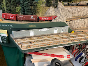
There was a long-standing woodworking company in Everett called E.A. Nord Co. (referred to as "Nord Door" by the locals) which shipped doors and other building supplies to contractors, sometimes by rail. Ray Wheeler told me that they used to spot boxcars there in the early '70's, and I believed him (as I usually do) and thought we should have a model of Nord Door near Bayside Yard in Everett. I mentioned this to Bill Messecar one day and he decided to scratch-build a representation of it for the tiny space I have for it up against a low section of backdrop on the north end of Bayside. The result is a great little removable piece of scenery with two doors to spot boxcars at. You can hear Bill describe how he made it on this brief video on YouTube, and here are a couple of pictures of the finished product:


And here's Bill with proof that it's removable...


Paving the Interbay Car Shed, Part 2


My first try at using EVA foam to model asphalt pavement between the tracks and rails in HO scale is progressing. As described in the previous post, I decided to try using black as the base color because it would take paint or pan pastels well, and any sort of unintentional blemish would not stand out like a sore thumb, like it does with plaster or other white materials. The one foot squares in the front of the photo are the 2mm thick pieces, for in between the tracks, and in the back is a roll of 1mm thick material, for fitting in between the rails. In truth, for the base layer, any material with about the same thickness as the height of the ties, such as balsa, styrene, cardstock, etc, would work - I just happened to have this material on hand and thought it would be easier to cut (which it was).

The first step was to prepare the surface between the tracks. In most cases it was bare cork ready-to-go, but along the front edges I had to use a putty knife and vacuum cleaner to remove some ballast and ground cover from next to the tracks, as shown below.

Then, I used a white chalk pencil to mark the edges of the 2mm thick black foam sheets, and a rotary knife to cut along the white pencil lines. The result was pieces of foam that fit between the track sections. I used white glue and various weights to glue these to the underlying cork roadbed:

The next layer was 1mm thick pieces to fit in between the rails. Similar process, same glue:


After removing the weights (again!) and testing the flangeways (they worked fine, thanks to the soft nature of the EVA foam), the next question was how to make it look like weathered asphalt instead of jet black foam. I decided to try blotching it with gray pan pastels using a make-up powder sponge. It turned out great!


I left the center part darker because it will be covered up by the car shops, in between the four square spacer blocks you can see glued on the foam. I thought about digging some inspection pits in there, but until I find out more prototype information about the actual building, I'm going to leave those details for a later time.

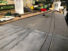
The last step (for now, anyway) was to pave the gravel areas on each side of the asphalt pavement, true to the prototype. This is the subject of a couple of YouTube videos you can watch, but in short, I applied Woodland Scenics fine grey ballast, leveled it off, cleared the flangeways, and carefully dribbled diluted white glue with an eyedropper to maintain the open flangeways while the glue dried. This also turned out pretty well, as you can see in both the above and below photos, although in retrospect I wish I had used real gravel dust instead of ballast, to get more of a variety of grain sizes in the pavement. It's certainly good enough for now. Here's the "final" product:

One last footnote - I noticed from Google Earth photos that the prototype kept the switchpoints clear of gravel pavement, so I did the same thing here, as you can see in the above photos and also below:


So now the car repair facility is paved! Next up will be putting all the equipment back, and possibly painting the building white like the prototype. Stay tuned, and I hope this motivates you to try some of your own paving projects.