Sunday, February 27, 2022

Push Buttons for Delta Wye and Vail Jct.

Without going into detail about how difficult it is to stoop down underneath a model train layout and connect up wires between push buttons and circuit boards, let's just say that significant improvements have now been made to make it easier for operators to control the three powered turnouts at Delta Wye and the very difficult-to-reach powered turnout on the narrow gauge line at what I fondly call "Vail Jct.", named of course after the legendary HOn3 modeler Jim Vail.

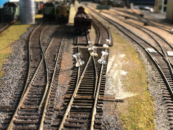
The reason I procrastinated on this job for so long (do I need a reason?) is that the wye needs to be operable from either side of the peninsula, meaning double push buttons and their associated wiring. Here is an overview of the wye area from each aisle, followed by a detailed view of the push buttons themselves.


This wye has been in operation for at least 20 years, with powered switch machines which I controlled with the "macros" on the NCE DCC throttles, and the single pair of push buttons to the very right of the lowest photo and a corresponding pair on the left of the photo above it. I was very proud of how well this worked, and as you can see I mounted a complex diagram on the fascia explaining which macro controlled which route. My operators, however, had a different experience. They would be trying to run a train through the area, and would not be the slightest bit interested in learning how to use the macros on the NCE throttles. In some cases it may have been their first experience even using an NCE throttle, let alone selecting a macro on it. So, prodded by a recent quip from operator Jim Betz, I spent about 6 hours setting all the needed pushbuttons up. So, having done that, I hereby apologize to all the operators here for the last 25 operating sessions for not having installed these in the first place! Argh!

It probably goes without saying that, once again, I have cut corners here significantly by not setting the push buttons in from the outside edge of the fascia. This means that operators will accidentally bump up against some of the pushbuttons at the wrong time and cause random derailments. Rather than spending the time to do it right in the first place, I seem to have chosen to wait and see how much of a problem it causes before investing any more time in it. Also, I probably should draw the track plan of the wye to connect the pairs of push buttons to make them easier to understand. Chalk pencils to the rescue, at a minimum!

The other thing that goes without saying is that the whole complex would benefit significantly from some red and green LED lights to indicate which way each switch is currently thrown. I hear you. That would be another 6 hours or more, not to mention the study and design time. I started looking at LCC and have all the equipment needed to advance this wye area to a much higher level of user-friendliness, but then put it all away in a box until other things with a higher "priority" get finished. One day I'll get back to that and you will be the first to read about it here. In the meantime, it's great to get these pushbuttons in, and many thanks to Jim Betz for spurring me on!

Tuesday, February 8, 2022

Adding a second deck - Part 3

With the completion of a working reversing loop, the famed (and arguably dubious) suspended second deck on the narrow gauge branch is officially in service. Here's how it looks today:


It looks a lot more finished than it really is. After painting the surface of the 1" Gatorboard base with brown latex paint and sprinkling it with Woodland Scenics turf blends, we grabbed four chunks of previously used extruded foam scenery, trimmed the corners to fit the turnback curve, touched up the exposed edges with more paint and turf, added some smaller trees for a "forced perspective" effect, and dropped the scenery pieces on top of the flat shelf. Magic! Here's a photo of the foam scenery pieces during paint touch-up, before putting them back on the layout:


In the distant background is one of the footstools that are pretty necessary to see and operate on the upper deck, which is too bad, but on the other hand it's great to have a place to run narrow gauge trains to, and have them be able to turn around and come back from. We decided to name the town "Opportunity" - partly because that's a real town near a famous smelter in Montana vaguely on the way between Washington State and Colorado, and partly because it fits in with the feeling of the other narrow gauge towns on this fictitious line - Paradise and Hope. 

"Track is scenery" means that I also took the time, after forming the flextrack pieces to the right curvature and length, to remove them to the spray booth and coat them with flat weathered-wood shade spray paint. Here's a picture of the peices drying on a bright yellow dropcloth afterwards, and the spray booth afterwards, before the final tracklaying:


Not shown are the ten switches, which I also spray painted in the booth before tracklaying. To lay the track on the Gatorboard, I drilled out small holes in some of the ties, the size of MicroEngineering medium spikes, and pushed the spikes through the ties into the top surface of the Gatorboard. I plan to go back and glue down the track more permanently with liquid latex after we've operated enough trains up there, and designed enough scenery and buildings, that we can commit to the track layout.

Speaking of operations, I also (somehow) found room on the front fascia of the deck below to install ten more car card boxes and labeled them appropriately. The town of Opportunity is officially open for business!


Friday, January 14, 2022

Adding a second deck - Part 2

 The second deck for the end of the narrow gage branch is coming along fine. In the previous post on this subject I was using a piece of 1x1 board to support the gatorboard pieces, but it seemed to me that it deflected too much under load, and I didn't want anything thicker to minimize the thickness of the deck. So I thought of using a steel beam, and consulted my neighbor who is a blacksmith, and while she had appropriate pieces of steel in stock, she advised that steel would be awfully heavy and suggested aluminum C channel would be good enough and much easier to drill holes in. So I bought some aluminum channel and mounted and leveled it. Also, I replaced those ugly steel straps with a couple of threaded rods, which seemed much easier to accurately level and adjust over time if needed. Then, since all of it would be underneath the upper deck, I primed and painted it all sky blue, as shown in the following photo:


After a few weeks of examining the gatorboard resting on the aluminum channels, I couldn't see any evidence of sagging or any other reason not to go ahead with the project, so I removed the three gatorboard panels and painted the bottoms sky blue and the tops with earth brown sprinkled with ground foam. It's so much easier to do painting like this at the workbench instead of up in the air! I also painted the fender washers I'll be using to hold the panels to each other with brown paint so they'll fit in with the scenery. All that's left is to paint the edges of the panels with my dark green fascia color, and I can put them back up on the girders. Here are a couple more progress photos of painting the panels:


In preparation for painting the edges, I applied lightweight spackle to the edges with a putty knife, to cover up the bare foam texture that might be too rough. Here's a photo of one of the fender washers painted with brown + foam:


So far, so good...


Saturday, January 8, 2022

Covering up a hideous wire run

If you finally get around to doing something that's been on your do list for at least 20 years, is that something to feel good about, or ashamed? I can't decide - I feel both. I guess it depends on how important the thing was. In this case, almost all of the layout track power wires were fed up to the ceiling joists and out to the rest of the layout from my centrally located DCC layout control system, next to a post, out in the open. They always needed some kind of a cover to hide them from view, but I never seemed to get around to devising one. Here's a picture of what it looked like, over on the right hand side of the photo:


It started bothering me more when I started publishing YouTube videos of the layout and the vertical column of tangled wires really disrupted the views of the otherwise nice (or at least acceptable) scenery. Then, as discussed in my previous post, we started installing an upper deck in the same area. This meant that the mess of wires would be an eyesore on both decks. Somehow, I couldn't live with it anymore. So, the fix is now designed and in progress. Help is on the way. We devised a plan to attach two inward-facing "C" aluminum channels at the corners of the post, and slide pieces of styrene between them, covering up the wires. Here's what it looks like now (with the upper deck temporarily removed):


Such an improvement! The next step will be to paint the whole thing with white primer and then sky blue, followed by scenic treatment such as trees and bushes. Then you'll never even know all those wires are in there. And if I need to add wires, it is easy to slide out the two styrene panels if needed for access (assuming I keep from sticking them together with paint). Progress!

Incidentally, the small maroon red box dangling to the left of the column is the transceiver for the BLI "Rolling Thunder" subwoofer system which needed relocating to accomplish this project. But the cable (in yellow) they provided literally fell apart when I went to relocate it, it was so cheaply made. So now I'm now hunting for a better cable, and hoping the system will work again. I don't use it very often though, because the low-frequency rumble that it generates makes the entire house shake, not just the train room. Probably an example of "too much of a good thing." Also, did I mention that the (exclusively) BLI decoders that work with it don't follow NMRA standards and are difficult to understand how to program? Don't get me started. I have only two BLI locomotives that work with it, and have no intention of ever acquiring any more. But at least BLI got me to mention them four times in one paragraph! I'll give them that.


Thursday, December 16, 2021

Adding a second deck for the narrow gage - Part 1


There's going to be a new narrow gage town on the Burrlington Northern soon! This just shows a mock-up, but there is more to come. The square hole in the backdrop, in the upper right hand corner of the photo, shows the current "end of track" where the narrow gage winds up a helix between some heading ducts. A short stretch of trestles and bridges will get it over to this proposed shelf, made of 1" Gatorboard. At the moment I am mocking up the proposed new upper deck, to see how it will affect lighting on the deck below and other considerations of feasibility and desireability. Here's a photo of it from below:


Of course we will paint the bottom sky blue to increase reflected light on the lower deck, and give it a backdrop, but as you will see in the photos below, thanks to the low angle of the already existing track lights, the effect of this massive shelf on the lower deck is surprisingly minimal. Here's another shot, taken from even higher than my 70" eye level:


This deck, at about 68" above the (slightly sloping) floor, will be visible at eye level to tall people like me, and operable by anyone with a suitable stool. It's an important strategic addition because it gives the narrow gage line "someplace to go" beyond the already exising intermediate towns of Paradise and Hope. In addition to this new town, I also plan to wrap the line around the corner to the left and build a combination staging yard and stock pen(s). There couldn't be a better time to work on this, because in Sept 2022 the National Narrow Gauge Convention will be held in nearby Tacoma and people from around the world might want to come egg me on. Or, maybe I could take one of the removable modules down to the convention for viewing. But, I'm getting ahead of myself...

Here's a final shot (for today) of that further addition mocked up - note how little it interferes with the lower deck lighting. The next step is to finalize the supporting brackets. One of my goals for the project is to have each of these shelves easily removable so we can do most of the modeling at the workbench rather than up that close to the ceiling. Any comments or suggestions are appreciated! I am really liking the dimensional stability of these 1" Gatorboard panels, but this is the first time I've tried using them for a layout base. Will keep you posted...


Thursday, November 4, 2021

Sand Towers at Interbay, Part 3

 Work continues on the Interbay Engine Terminal's sand tower project. Here is an overview from the south looking north, showing that I removed one of the existing tracks and replaced a number 6 switch with a wye switch, in order to make room for a concrete pad to support the sand towers. Dave Enger built the pads out of sheet styrene, which you can see are temporarily in position. The BN mainline is the track to the left of the construction site, with grey ballast and raised above the rest of the yard.


Here is a detail view of the approximate track alignment, showing that we'll have to cut part of the concrete pad to accommodate the curving track


And finally, here is a view from the north looking south, showing that we've added a new turnout to provide a short track for loading sand, oil and water to the various dispensers that will be on the locomotive service pad. I doubt this track was there on the prototype in this exact location, but it's where we have room for it, so there it is. It will be fun to spot cars there during op sessions. Especially since we have a model of Northwest Olivine on the Concrete Branch, which was the source for this high quality locomotive sand, making it one of those rare prototypical on-layout origin/destination pairs.


Monday, November 1, 2021

Sand Towers at Interbay, Part 2


Here's a better close-up of the Interbay sand towers that we're trying to model. One early design decision we had to make was how far north or south to located them in my condensed HO scale version of the Interbay Engine Terminal. Below are two photos, with the mocked up towers positioned to the right (south) and left (north). We didn't consider going all way to the north, because I wanted to allow room for a short spur for unloading sand cars. More on that in a later post.


Based on these mock-ups, we've decided to locate it to the right, as shown in the upper photo here. Next up will be to install the concrete pavement between the tracks and re-install the track.