Monday, August 23, 2021

Paving the Interbay Car Shed, Part 1

 What's the quickest and easiest and best way to pave the surfaces between the rails and tracks at the Interbay Car Repair Facility, now that I've removed all the locomotives and cars (which hopefully you already enjoyed in this quick video short on YouTube)? Here's an aerial shot of the whole area to be paved, which you can see is pretty large:


In the past, for paving streets, I've used (1) "lightweight spackle", (2) plaster, (3) sheet styrene, and (4) sanded grout. Here is my experience with each:

(1) I painted the lightweight spackle a gray acrylic, which looks ok, although a bit uniform for my taste, but I find it's easy to accidently gouge it with your fingernails or with a track cleaning tool, and then the white spackle shows through. I suppose I could make it less uniform with washes and pan pastels. The same is true for all the other methods, too.

(2) Plaster has the same gouging issue, and also can crack over time. I suppose you could add dye to it and make it the pavement color throughout, but again it would be too uniform in color. And I'm looking for something quick and easy, not a plaster dyeing project.

(3) Sheet styrene is durable, paintable, easy to scribe cracks into, and not subject to changes over time. But, it takes a lot of work to cut each piece to fit. It's not quick and easy.

(4) Recently, we've been trying sanded grout, in various shades of gray. You can putty it on like plaster, and it dries rock hard. Rock hard. You can't gouge it with anything other than tool steel - it's reconstituted rock, once it sets. So getting it out of the flangeways of the track, and below the railhead, is important if you want reliable operations with DCC. We did this while it was setting, but when I came back the next day it seemed to have slightly expanded in the final stages of setting. It was a real job getting the rails clean enough to have reliable electrical contact. The surface looks pretty good, although a little shiny for my taste, and I may need to go over it again with some pan pastels one day. Also, if you don't use pre-mixed grout, you have to get the proportions of water and dry grout just right, or the thing will not set up right. I suppose you could dribble the diluted fixative of your choice on it afterwards. This isn't sounding quick and easy either.
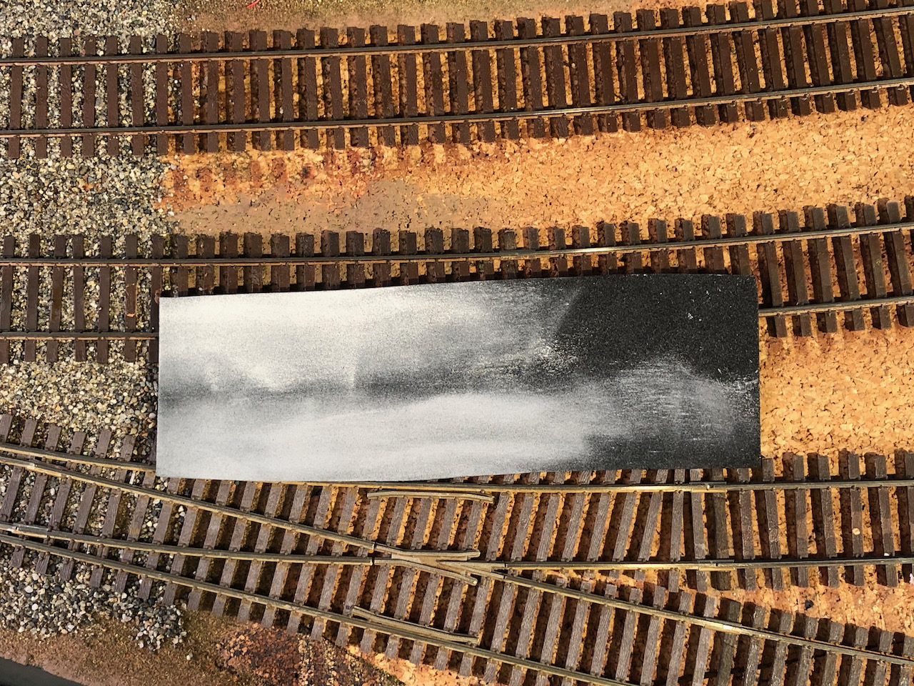

So, I'm game to try something new. Above you see a sample of a product that's easy to cut, glue, paint and weather. It's called "PVC foam", and I heard about it from Al Frasch and some other online NMRAx clinics. It's denser than regular "foam rubber", but it cuts easily with a knife and comes in thicknesses down to 1mm. This is good, because the height of my code 70 rail is .070 inches which equates to 1.8mm. (code 83 is about 2.1mm and code 55 is about 1.4mm). But the stuff you can buy in a regular craft store is usually just the 2mm thickness. 2mm would work fine for areas of code 83 rail, but in this case I need it to be a little less, so I ordered some 1mm foam online in order to try it. I don't really want the foam (or anything else) sticking up above the railheads, so stay tuned for the experiment. Al is using 2mm foam for pavement on his N scale layout, on the code 75 Atlas track, which should be about perfect. He claims that the loco wheels push the foam down and he has no problems with it. I might try an experiment with the 2mm foam, but first I want to try the 1mm foam and see how it works.

The other thing is how to color it. I could spray paint the whole sheet with a gray primer, but then would it curl up over time, or be hard to glue evenly? What you see above is that I tried a couple of shades of pan pastel on it, and I'd say it looks great. I can just glue it down black, and come back and create a realistic uneven gray using several shades of pan pastel.

Above, you see a single piece of 1mm PVC foam cut to fit the entire area. I should be able to cut it in strips with an Xacto knife without to much effort, and glue it down with white glue and some weights.

But let's not get ahead of ourselves - the areas between the tracks need to be raised up to the height of the ties first. We'll get to that in my next post. So much for quick and easy, huh?


Saturday, August 21, 2021

Laying track and switches at Interbay Car Shop's north end ladder

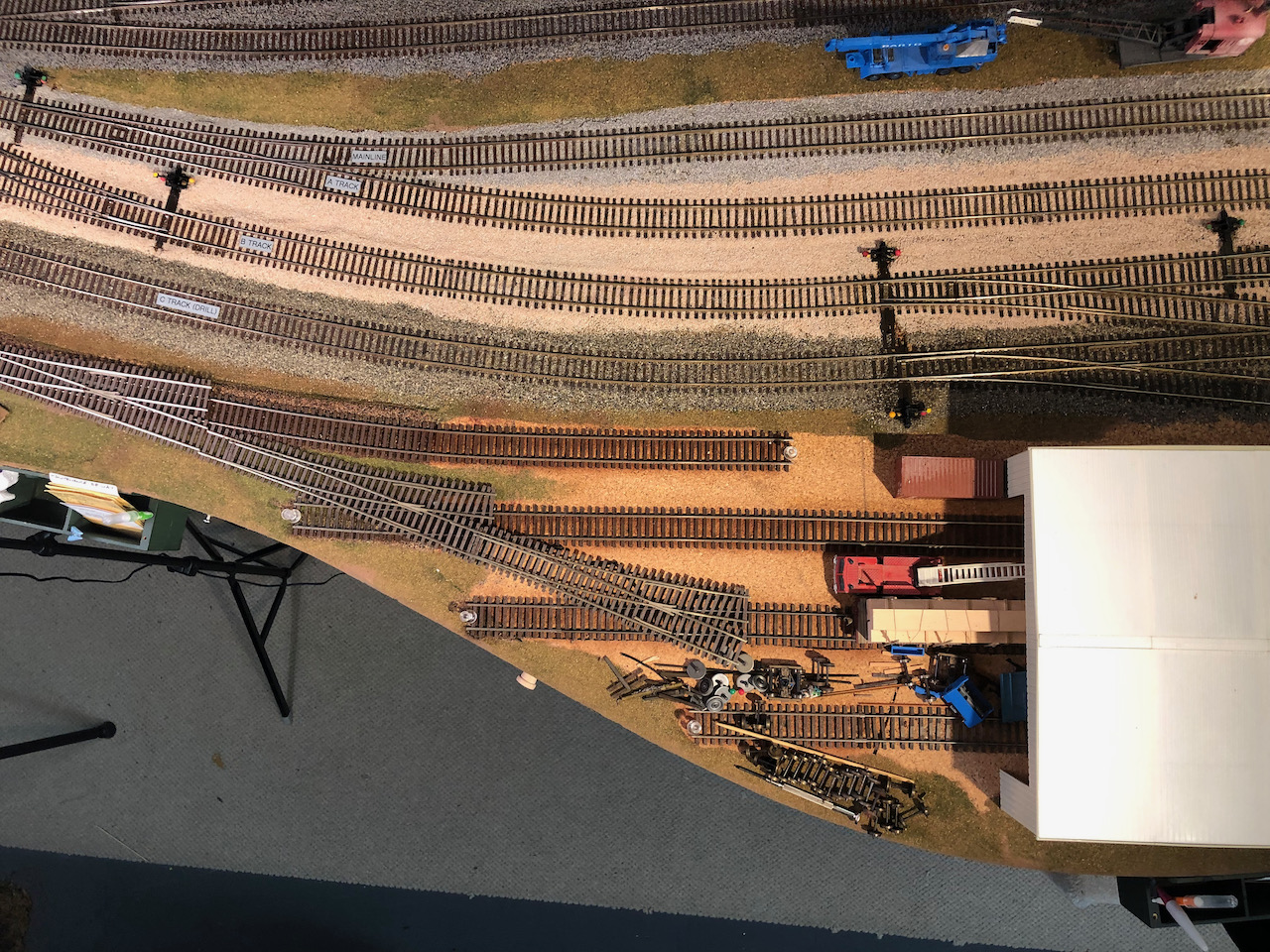
Here's a view of the north end of the Interbay Car Repair Facility in Seattle on my HO scale Burrlington Northern model railroad, set in 1973, which is probably around the time that they built this modern three-bay car shop. The prototype facility has a ladder on both sides, but for many years I was satisfied with the tracks simply coming into the building from some switches on the other side and stub-ending on this side, as you can see in this photo, underneath the new Micro-Engineering switches that I've laid out on top of them. 


For the last week, I've been working on installing these three switches. You can watch a YouTube live stream where I describe rail-filing and rail joiners at this link. For the rest of this post, I'll just show some more still photos of the progress so far. Here's an aerial photo of the area on my layout, which more clearly shows the existing straight tracks and my desired layout of switches to connect them.


The first step was to remove the existing track, as needed. This was relatively easy, because I use liquid latex to glue down my track, so I can generally just reach underneath with a putty knife, as shown here, and lift the tracks up if I need to relocate them, such as I need to here.


Unfortunately, I had already ballasted the lead to this ladder, so I needed to wet down the ballast (held in place by water-soluble white glue) in order to cut some of the track and curve some of it.


But, I'm happy to say, wetting down the old section of ballasted track and curving it slightly to the right worked fine, as you can see in the next photo:


The next step was to carefully align the track, hold it with push pins, and apply drops of liquid latex (diluted about 3:1 with water), and press the track down with weights as needed for vertical alignment. You can see that the mainline was temporarily out of service while I used it for storing the car repair shed and other tools and supplies.

After eight hours, when the liquid latex was dry, I came back and applied ballast to the area and glued it down with diluted white glue. When that dried, I installed Red Caboose ground throws (#206S has the right amount of throw for these Micro Engineering turnouts), painted their targets to match the opposite push-pin "faux-signals", cleaned the tops of the rails one more time with a bright-boy eraser, and did some final testing. So far so good. Now, if I could just find the craft foam that I bought to pave the tracks in and near the car shed, I would continue on with that phase of construction. Stay tuned. It's got to be here somewhere!


The other thing I need to do is figure out the operating implications of these new switches. Can I use this side of the shed for storing switch engines and, of course, the "big hook"? When cars are repaired, do they come out this side and need to be switched back into the main yard? What do you think?


Friday, July 16, 2021

Our first ops session since Covid


With very little notice, we put together a small operating session on July 5, with a total of 8 vaccinated operators in the room for about 3 hours. Chuck Hakkarinen was visiting the area from his home in CA, and asked me if there were any op sessions going on, so we created one with only 48 hours notice! I was surprised how many people said yes, and how quickly. We are all looking forward to getting back to operating sessions soon. Chuck is the one with the polka-dot hat in the photo below, with Tim Taylor managing the Delta Yard area as usual:


 Jim Betz, from Burlington, WA, ran the GWS south from Bellingham to Seattle, while Lee Marsh managed the Stacy St. yard and Anita Taylor ran several through freights.


Todd VonStup did a great job as Interbay yardmaster, while Dave Enger and I did roving assistance as needed. We were all grateful to Chuck for asking the question!

I took a few handheld cellphone video clips at various times, and consolidated them into a YouTube video that you can watch here. I'm not quite ready to schedule the next op session, but it seems like we're getting closer, if there isn't another Covid spike in August brought on by people refusing to do the right thing and get vaccinated. Come on, people!


Thursday, June 24, 2021

Removable scenery and B's Cafe


I'm a big proponent of removable scenery, and have many examples on my layout that are vital to its long-term success. For example, it's great to be able to take the top off a mountain if you need to clean the track inside a tunnel. This week, my example is a shelf above the narrow gage staging yard in Everett. I wanted to have a four-track staging yard to store narrow gage trains, but the area above it also needed to represent the Cascade Copper Co. mine, at the end of a narrow gage branchline. If there were derailments inside the staging yard, I needed to be able to get at it, but otherwise the space above it was perfectly good "real estate" ready to be developed. 

After several years of staring at an odd-shaped piece of foam only partially covering the staging yard, I asked my friend Eric Vannice for his thoughts. The next thing you know, he had crafted a detailed piece of scenery designed to fit over the staging yard. Here he is proudly standing next to his masterpiece:


One of the challenges with removing removable scenery is what to grab onto to remove it without damaging the scenery. Eric thought of making a small, vital, solid wood structure, screwed into the base, so you could grab the scenery by the building! Here's a picture of the screw holding the building firmly into the underside of the scenery base:


I won't be able to add a detailed interior to this particular building, but it looks great as it is! My wife and I both have names starting with "B", so this is arguably the obvious choice for this establishment, which will be well patronized by the miners at the nearby Cascade Copper Co. mine. I'll plant some HO scale picnic tables out in front of it and see how fast those hungry miners show up.

You'll also notice (above in the picture with Eric) that the rock molds in the removable scenery match the nearby rocks. Many years ago, when Eric was making the original scenery to the right of this removable piece, he suggested we cast some extra plaster rocks from the same molds we were using "just in case". I kept them in a drawer under the layout all this time, and now here we were with a perfect use for them. It turns out that being a model railroad pack rat sometimes pays off!

Below is a final (for the moment!) shot of this shoehorned piece of real estate next to a locomotive. Another thing that worked out well is placing the building in front of the shadow line. Right where the shadow line is I plan to put a gravel road and a few period vehicles, to further distract the viewer from the shadow of the deck above. Not to mention install some more of those rocks below the track where the locomotive is standing. And a few trees in the back. Perhaps if the trees in the back of the insert are a lighter color, it will dilute the visual effect of the shadow. A model railroad is a never-ending quest!

This blog post inspired me to do a YouTube video about removable scenery, which you can enjoy here.


Sunday, June 13, 2021

A little construction progress


 We started slowly back to having "Train Days" on Tuesdays, mostly work parties with breaks for random fun with train running. Tim applied some Automatic Car Identification (ACI) labels to cars and locomotives, to help establish our time frame of about 1973. Above, you can see one of the newly-arrived Athearn Genesis GP-18 locomotives with the ACI label underneath the "F" in "PACIFIC". This locomotive clearly fits in that time frame, having been renumbered for the BN after the merger in 1970, but not having been repainted BN green, which would have happened well before 1977. In this case, we put the ACI labels on both sides of the engine, but with freight cars we're only applying it to one side, in case some day we want to run trains in the eras either before or after the ACI craze.

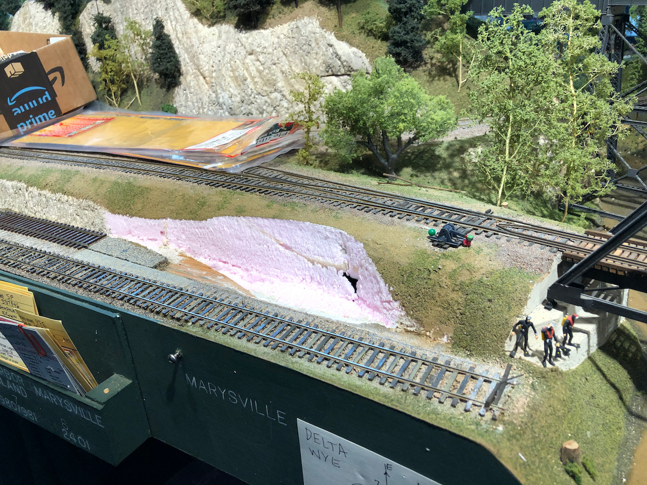
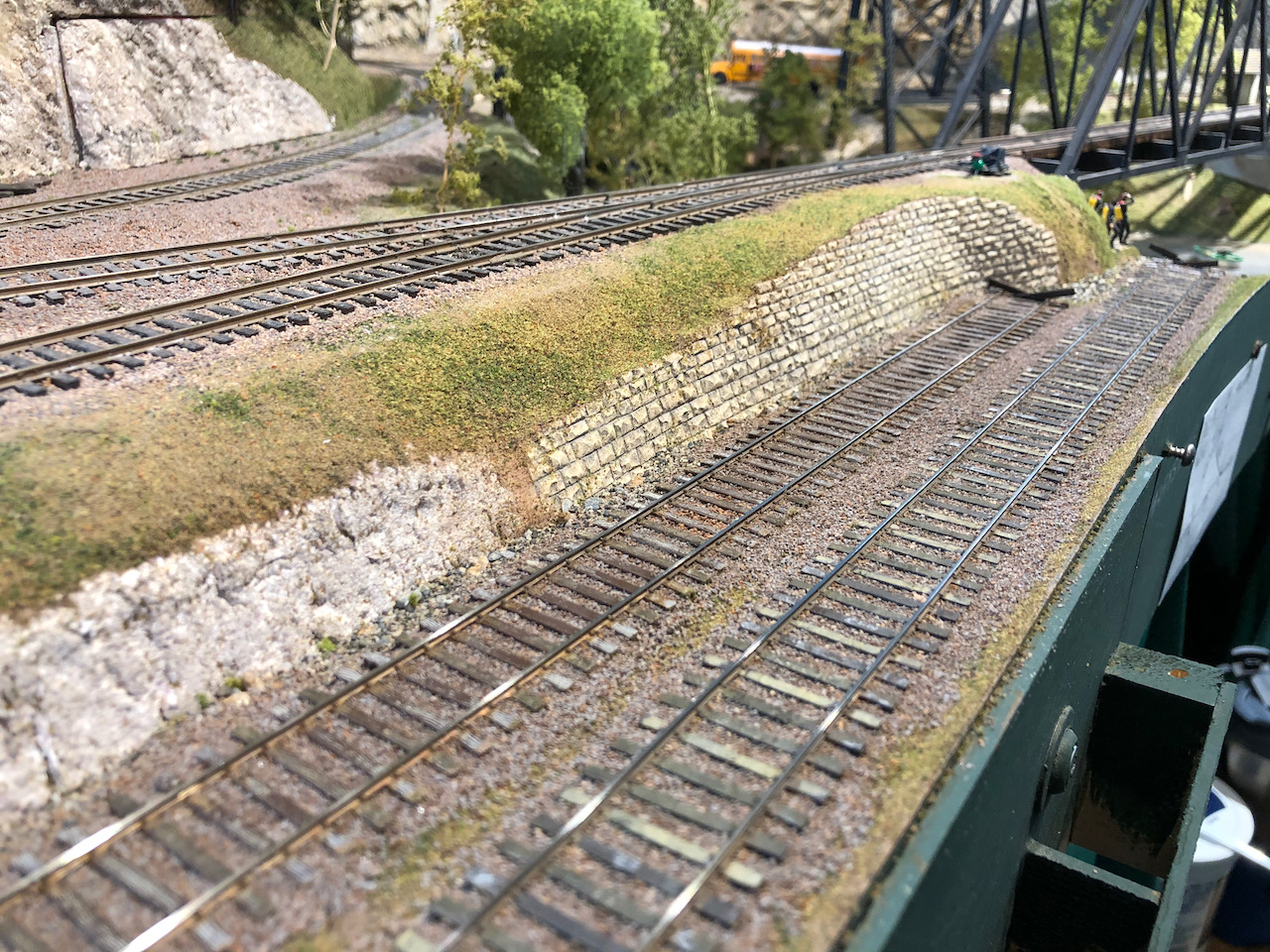
Dave, on the other hand, has carried out a couple of track and scenery improvements. The first was to lengthen the "Marysville" spur, which we use as a staging track to represent industries in Marysville, just north of, and across the river from, the main yards in Everett. There is no end to the effort that model railroaders will put into adding additional track capacity, and this was no exception. We carved up a perfectly good sloping hill and replaced it with a Chooch retaining wall in order to lengthen the track by about ten inches. Before and after photos shown below:


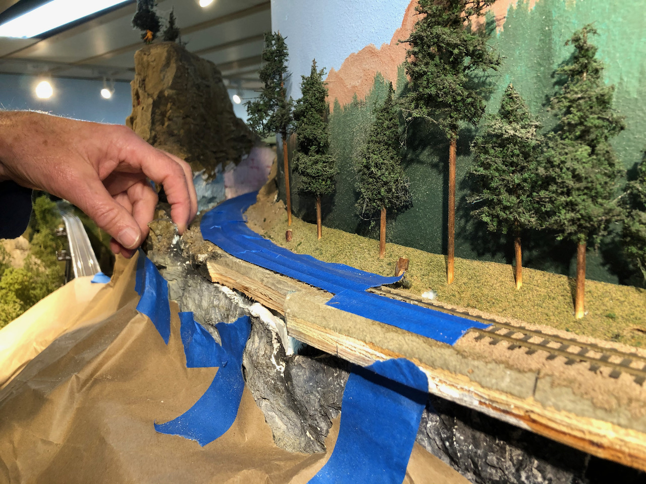
Along the narrow gage line, there was a curve behind the "Needles" rock outcropping that was bare blue and pink foam, ever since I reworked the grade in that area (5 years ago?) to clear double-stack trains in the standard gage tunnel below. Dave carved Sculptamold to match the cast plaster rocks above, and then colored it with acrylic washes. Then I came in with dirt and scree along the side of the tracks, glueing it down with diluted liquid latex on the ballast and diluted white glue on the scree. Mission accomplished!


Thursday, April 29, 2021

Fun with MILW trackage rights on my BN Seattle Region HO layout

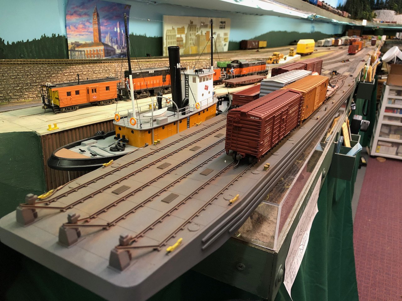
You bring the MILW coast train down to Seattle from Bellingham on BN trackage rights, interchanging with BN at Everett and again at Argo in South Seattle, and head into "Tacoma Tideflats" staging. Then you take a MILW switcher and sort out everything you have in Argo yard (including interchanging cars with UP, which also uses Argo). Then you take a cut up to the Pt. Townsend car barge slip near Stacy St. yard and unload/load the car barge, returning to Argo to sort it all out. Then you take any cars up and back from the MILW freight terminal east of Stacy St. yard against the backdrop and the aforementioned auto loading tracks at P90/91 on the west side of Interbay yard, and return to Argo yard again, and make up a cut for the northbound MILW coast train. You then park the switcher for the day, and bring in a northbound MILW coast train from staging (perhaps the same one you started with, which you might have turned and backed into staging earlier). Pick up your northbound cars from Argo, head to Everett, do another interchange move if needed, and run to Bellingham staging. Oh, and did I mention that while switching Argo you do an interchange transfer run to/from the BN at Stacy St. yard? Or that you do all this while staying out of the way of all BN operations? Whew - that's a long (and interesting, in my opinion!) day!!


Wednesday, March 24, 2021

Are my SPINS diagrams overkill?


Are you familiar with the prototype SPINS documents? I think they've been uploaded to the Pacific Northwest Rail Archive, although I haven't actually looked for them there yet. The FOBNR website may have them too. What I did was to find the diagrams (and shipper names) for the areas of the railroad that I model on my layout, and then re-draw them (in a PowerPoint document) so they used a similar layout and numbering system, but were correct track diagrams for my actual layout. I printed them all out into a booklet for operators, and then I took one of the booklets and cut the maps only out and pasted them on the front fascia. Whenever I make a track change, I'll edit the PowerPoint file, update the operator handbook, and paste up a new map on the fascia. Sometimes this also involves making some new waybills to reflect the new SPINS codes I've added. 

Are you a member of the OPSIG? The April 2021 issue of their (excellent) magazine has an interesting article about using car tabs instead of waybills, and of particular interest is his suggestion to simplify ops by using just a two digit code for each unique spot - the first digit being the town and the second digit being the industry. In (perhaps foolish) contrast, by carefully copying the prototype SPINS setup, I am using a six digit code: two digits for the "zone", two digits for the "track" and two digits for the "spot" on that track. I believe the prototype may have had two more digits at the beginning of the code for the "region", for a total of eight digits, but since all of my railroad is in the Seattle Region I decided to leave those first two digits out of the system altogether (even though the prototype would have used all eight in their documents). I put these six digit SPINS codes on all my waybills, so an operator can simply sort the car cards by SPINS number and the train is automatically blocked. A cool idea, but only a couple of operators have actually figured out and used this method in the five years since I've been using it.

I think what I'm trying to say is that copying the prototype SPINS diagram on the fascial looks cool in a magazine, but may be overkill in practice on a real model railroad. The more I try to carefully copy the prototype, the more I run into situations where I need to back off and do what makes it the most fun for operators. Another example of this is weighing cars - I built track scales in Interbay and Stacy St. yards in Seattle, but yardmasters almost never use them because there is always too much more important work to do. They just park cars on the scale tracks like any other yard track, because there are never enough yard tracks!

That said, I'm very proud of my faux-SPINS diagrams and they do give a slightly more prototypical feel to the operation. The feedback I've gotten from operators is that they would like me to put building outlines and labels in the diagrams so it was easier to find something like "Scott Paper" without having to look it up in the handbook and find the number on the map. My plan is to do a major revision of the whole thing with shipper names on the maps instead of just the SPINS numbers. Then the SPINS diagrams won't look as realistic, but they'll be easier to use. Also, the switch numbers and the track numbers are redundant, so I might pick one or the other and eliminate 50% of the visual clutter in the maps. 

Here's a picture of the SPINS diagram mounted on the front fascia of the layout, at Burlington. It really does seem like it would be better if the names of industries were shown on the diagrams, instead of just all those numbers!


I mentioned that I left off the first two digits representing the division, but the more I think about waybills and ops, it sort of bothers me that I don't have an easy way to code for, say Kansas City vs. say Minneapolis. I used to think that heading east over Stevens Pass was all I needed to know about a car or a train, because my layout only goes as far east as Skykomish, but now I'm realizing that they had Laurel blocks and Minot blocks, and these were combined at Hillyard in Spokane with similar blocks from Portland to make the through trains complete. So even though I have Zone 54 set up as Skykomish, I'm thinking about adding some additional Zones to represent the through blocks that would have been set up by the yardmasters in Interbay. That would work, but, again, would my yardmasters pay any attention to it whatsoever, when they're slammed already just trying to get the eastbound cars out of their yard? Probably not. So it's probably not worth it. I'm just thinking about it. The good news is that having a two digit code for zones gives me a lot of flexibility compared with a one digit code.